Toyota prius 3rd gen Weight Detection Sensor Assembly (W1)(W4)(W6)(W7)
Toyota Prius 3 rd Generation (XW30)
Toyota Prius 3 rd Generation (XW30) Weight Detection Sensor Assembly Wiring Guide: DIY Pinout Diagram


1. Introduction
The Toyota Prius 3rd Generation Weight Detection Sensor Assembly is a seat-mounted sensor located in the front passenger seat cushion. It measures the occupant’s weight and sends signals to the Occupant Detection ECU, allowing the SRS system to determine airbag deployment—preventing unnecessary or dangerous airbag activation for children or light passengers.
- Seat Cushion Sensors :- strain gauges or pressure sensors embedded in the seat foam/frame.
- Sensor Wiring Harness :- connects sensors to the Occupant Detection ECU.
- Connector Plug :- for ECU communication.
- Mounting Brackets/Frame :- secures sensors inside the seat.
- Calibration/Signal Module :- sometimes integrated to stabilize sensor readings.
2. Weight Detection Sensor Assembly Wiring Diagram & Pinout
A. Connector Location
- Sensor Position: inside the front passenger seat cushion, mounted on the seat frame under the seat foam.
- Connector Type:
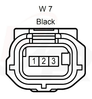
- W1 (3 pin) Gray housing
- W4 (3 pin) Black housing
- W6 (3 pin) Gray housing
- W7 (3 pin) Black housing
B. Wiring Table
Weight Detection Sensor Assembly (W1) (W4) (W6) (W7)
W1 TERMINALS OF Rear In Weight Detection Sensor Sub–Assembly CONECTOR
| Terminal No | Symbol (Pin Definition) |
Wiring (Color Code) & Color |
Electrical Paths |
|---|---|---|---|
| W1-1 | 1 |
(GR) Gray |
|
| W1-2 | 2 |
(SB) Sky Blue |
|
| W1-3 | 3 |
(W) White |
|
W4 TERMINALS OF Front In Weight Detection Sensor Sub–Assembly CONECTOR
| Terminal No | Symbol (Pin Definition) |
Wiring (Color Code) & Color |
Electrical Paths |
|---|---|---|---|
| W4-1 | 1 |
(R) Red |
|
| W4-2 | 2 |
(P) Pink |
|
| W4-3 | 3 |
(G) Green |
|
W6 TERMINALS OF Front Out Weight Detection Sensor Sub–Assemb CONECTOR
| Terminal No | Symbol (Pin Definition) |
Wiring (Color Code) & Color |
Electrical Paths |
|---|---|---|---|
| W6-1 | 1 |
(W) White |
|
| W6-2 | 2 |
(L) Blue |
|
| W6-3 | 3 |
(LG) Light Green |
|
W7 TERMINALS OF Rear Out Weight Detection Sensor Sub–Assembly CONECTOR
| Terminal No | Symbol (Pin Definition) |
Wiring (Color Code) & Color |
Electrical Paths |
|---|---|---|---|
| W7-1 | 1 |
(V) Violet |
|
| W7-2 | 2 |
(B) Black |
|
| W7-3 | 3 |
(BR) Brown |
|


.png)


Comments
Post a Comment