Toyota prius 3rd Gen Fuel Injector Assembly (14)(15)(16)(17)
Toyota Prius 3 rd Generation (XW30)
Fuel Injector Assembly Wiring Guide: DIY Pinout Diagram

Toyota Prius 3rd gen fuel injector assembly front view, part number 23250-37010

Side view of Toyota Prius 23250-37010 fuel injector assembly

Complete fuel injector assembly for Toyota Prius hybrid engine
1. Introduction
The Toyota Prius 3rd Generation (23250-37010) is a precisely engineered component designed to deliver the exact amount of fuel into the engine for clean and efficient combustion. It plays a vital role in the Prius hybrid system by ensuring optimal fuel atomization, stable engine idling, and improved fuel economy. Controlled by the Engine Control Unit (ECU), this injector adjusts fuel delivery based on driving conditions, temperature, and load. Its durable construction helps maintain low emissions and consistent engine performance. Proper functioning of the injector assembly is essential for smooth acceleration, reduced fuel consumption, and maintaining the Prius' renowned eco-friendly driving experience.
- Engine Control Unit (ECU/ECM) :-Controls the injector timing and pulse width for accurate fuel delivery.
- Fuel Rail :- Distributes fuel evenly to all injectors under high pressure.
- Fuel Pump & Fuel Filter :- Supplies clean, pressurized fuel to the injector assembly.
- Air Intake System (Throttle Body, MAF Sensor) :- Works with fuel injection to maintain the correct air-fuel ratio.
- Oxygen (O₂) Sensors :- Monitor exhaust gases to help ECU adjust fuel injection.
- Engine Coolant Temperature Sensor :- Influences fuel delivery based on engine temperature.
- Intake Manifold & Combustion Chamber:- Where the fuel is injected and mixed with air for combustion.
2. Fuel Injector Assembly Wiring Diagram & Pinout
A. Connector Location
- Fuel Injector Assembly Position: located on the engine’s intake manifold, directly above the cylinders.
- Connector Type:
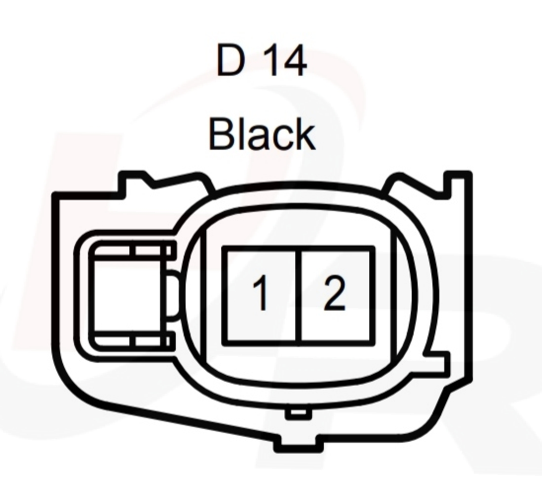
- D14 (2 pin) Black housing
- D15 (2 pin) Gray housing
- D16 (2 pin) Black housing
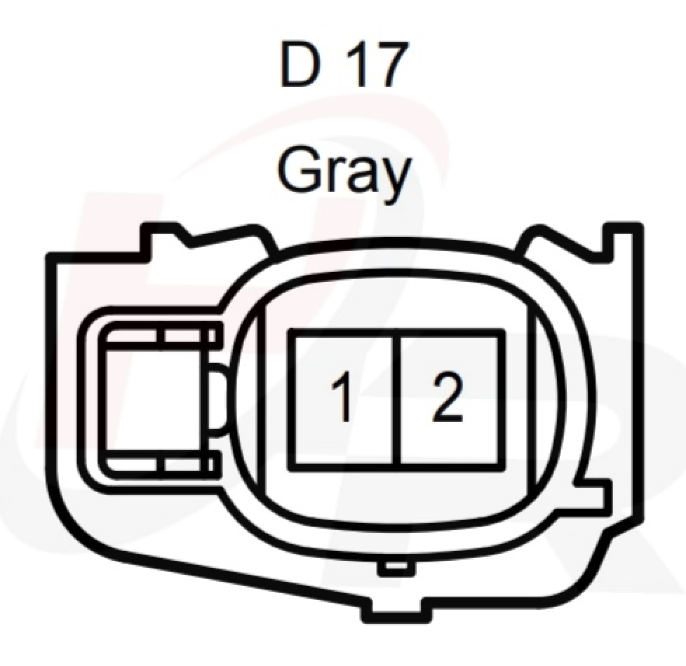
- D17 (2 pin) Gray housing
B. Wiring Table
Fuel Injector Assembly (D14) (D15) (D16) (D17)
D14 TERMINALS OF Fuel Injector Assembly No.1 CONECTOR
 |
|||
| Terminal No | Symbol (Pin Definition) |
Wiring (Color Code) & Color |
Electrical Paths |
|---|---|---|---|
| D14-1 | 1 |
(B) Black |
|
| D14-2 | 2 | (Y) Yellow |
|
D15 TERMINALS OF Fuel Injector Assembly No.2 CONECTOR
 |
|||
| Terminal No | Symbol (Pin Definition) |
Wiring (Color Code) & Color |
Electrical Paths |
|---|---|---|---|
| D15-1 | 1 |
(B) Black |
|
| D15-2 | 2 | (B) Black |
|
D16 TERMINALS OF Fuel Injector Assembly No.3 CONECTOR
 |
|||
| Terminal No | Symbol (Pin Definition) |
Wiring (Color Code) & Color |
Electrical Paths |
|---|---|---|---|
| D16-1 | 1 |
(B) Black |
|
| D16-2 | 2 | (L) Blue |
|
D17 TERMINALS OF Fuel Injector Assembly No.4 CONECTOR
 |
|||
| Terminal No | Symbol (Pin Definition) |
Wiring (Color Code) & Color |
Electrical Paths |
|---|---|---|---|
| D17-1 | 1 |
(B) Black |
|
| D17-2 | 2 | (R) Red |
|

.png)
.png)
Comments
Post a Comment