Posts

Toyota prius 3rd Gen E. F. I. Vacuum Sensor Assembly (D3)

Image
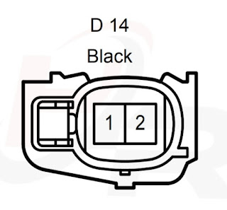
Toyota prius 3rd Gen E. F. I. Vacuum Sensor Assembly (D3) (89421-47010) Toyota Prius 3 rd Generation (XW30) E.F.I Vacuum Sensor Assembly (D3) D3 TERMINALS OF E.F.I Vacuum Sensor Assembly CONECTOR Terminal No Symbol (Pin Definition) Wiring (Color Code) & Color Electrical Paths 1 PIM (B) Black ➔ D28 69 (PIM) [Engine Control Module] 2 EL (Y) Yellow ➔ D28 71 (EPIM) [Engine Control Module] 3 VC (L) Blue ➔ D28 72 (VCPM) [Engine Control Module] 4 _ _ _ Go back

Toyota prius 3rd Gen Fuel Injector Assembly (14)(15)(16)(17)

Image
Toyota prius 3rd Gen Fuel Injector Assembly (D14)(D15)(D16)(D17)(23250-37010) Toyota Prius 3 rd Generation (XW30) Fuel Injector Assembly (D14) (D15) (D16) (D17) D14 TERMINALS OF Fuel Injector Assembly No.1 CONECTOR Terminal No Symbol (Pin Definition) Wiring (Color Code) & Color Electrical Paths 1 1 (B) Black ➔ ✠ ➔ DA2 6 ➳ ✠ ➔ 1A 4 ➤ [IG2 Relay] 2 2 (Y) Yellow ➔ D28 85 (#10) [Engine Control Module] Go back D15 TERMINALS OF Fuel Injector Assembly No.2 CONECTOR Terminal No Symbol (Pin Definition) Wiring (Color Code) & Color Electrical Paths 1 1 (B) Black ➔ ✠ ➔ DA2 6 ➳ ✠ ➔ 1A

Toyota prius 3rd gen Headlight Dimmer Swich Assembly (L47)

Image
Toyota prius 3rd gen Headlight Dimmer Swich Assembly (L47) (84140-42070) Toyota Prius 3 rd Generation (XW30) Headlight Dimmer Swich Assembly (L47) L47 TERMINALS OF Headlight Dimmer Swich Assembly CONECTOR Terminal No Symbol (Pin Definition) Wiring (Color Code) & Color Electrical Paths 1 _ _ _ 2 _ _ _ 3 LFG (Font Fog Light Swich Common GND Pin) (L) Blue ➔ 3A 69 ⇔ 3A 68 ➔ L47 12 (EL) [Headlight Dimmer Switch Assembly] ➔ 3A 69 ⇔ 3A 67 ➔ L93 5 ⬌ L93 3 ➔ ▼ L1 (Ground Point) 4 BFG (Font Fog Light Swich OutPut Pin) (LG) Light Green ➔ L7 27 (FFOG) [Main Body ECU] 5 _ _ _ 6 _ _ _

Toyota prius 3rd gen Combination Meter Assembly (L27)

Image
Toyota prius 3rd gen Combination Meter Assembly (L27) Toyota Prius 3 rd Generation (XW30) Combination Meter Assembly (L27) L27 TERMINALS OF Combination Meter Assembly CONECTOR Terminal No Symbol (Pin Definition) Wiring (Color Code) & Color Electrical Paths 1 _ _ _ 2 TC O (G) Green ➔ L57 1 (CS) [Tip Switch Assembly] 3 TIRE (Tire Pressure Warning Inductor) (G) Green ➔ L4 5 (IND) [ Tire Pressure Warning ECU ] 4 _ _ _ 5 S ( Engine Oil Pressure Inductor) (R) Red ➳ AL1 20 ➳ DA1 16 ➔ D26 1 [ Engine Oil Pressure Switch Assembly ] 6 LVWG (Head Light Leveling Indicator) (L) Blue ➳ AL7 3 ➔ A48 6 (WNG) [ Head Light Leveling ECU Assem